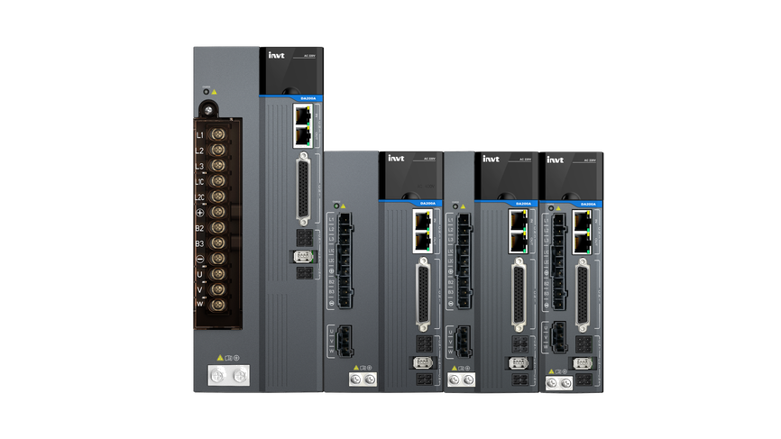

| DA200A series servo drive | ||||
| Specification | Description | |||
Power supply | System input voltage of 220V | 1PH/3PH AC200V–240V47Hz–63Hz | ||
| System input voltage of 400V | 3PH AC380V–480V 47Hz–63Hz | |||
Port | Control signal | Input | 10 inputs for standard type, 7 inputs for bus type servo (the function can be configured by relevant parameters). Input range:12–24V; Input bandwidth: More than 1k. Switching delay: Less than 5μs | |
| Output | 4 differential outputs for standard type and EtherCATbus type(the function can be configured by relevant parameters). Output range:12–24V; Output bandwidth: More than 1k. | |||
Analog | Input | 212-bit inputs, input range: -10V–+10V. | ||
| Output | 2 outputs (analog monitoring output), output range: -10V–+10V, 12-bit resolution. | |||
Pulse signal | Input | 2 differential inputs, Puls+Sign. Indicator: Differential input 4Mbps, open collector input 200kbps. (High-speed optocouplerwith high signal-noise rejectionratio) | ||
| Output | Six outputs (3 differential outputs, 3 open collector outputs) | |||
First encoder | Input | Two-wire and four-wire absolute encoder interfaces (Tamagawa, Nikon, BISS and EnDat2.2). Indicator:Max. baud rate of absolute encoder 5Mbps | ||
Secondencoder | Input | Incremental encoder (Second encoder or fully-closed loop linear encoder), indicator: Max. quadrature input frequency 12Mbps, supporting ABZ disconnection detection function | ||
Communication | USB | 1:1 communication upper PC software (standard, Type-C) | ||
| RS485 | 1:n communication (standard) | |||
| CANopen | 1:n communication (optional) | |||
| PROFIdrive | 1:n communication (optional) | |||
| EtherCAT | 1:n communication (optional) | |||
| Safety terminals | STO | Safe torque off (conform to the latest European safety standards SIL3) (optional) | ||
| Control mode | 1. Position control; 2. Speed control; 3. Torque control;4. Position/Speed mode switching; 5. Speed/Torque mode switching; 6. Position/Torque mode switching; 7. Fully-closed loop control; 8. CANopen mode; 9. EtherCAT mode | |||
Function | Position control | Control input | 1. Clear residual pulses 2. Disable command pulse input 3. Electronic gear ratio switching 4. Vibration control switching | |
| Control output | Positioning completion output, etc | |||
| Pulse input | Max. pulse input frequency | Optical coupling: differential input 4Mpps, open collector input 200kpps; | ||
| Pulse input mode | 1. Pulse + direction; 2. CW+CCW; 3. Quadrature | |||
| Electronic gear | 1/10000–1000 times | |||
| Filter | 1. Command smoothing filter; 2. FIR filter | |||
| Analog input | Torque limit command input | Can independently perform clockwise/counterclockwise torque limit | ||
| Vibration control | Able to suppress 5–200Hz front-end vibration and overall machine vibration | |||
| Pulse output | 1. Can perform arbitrary frequency division settings under the encoder resolution; 2. B phase reverse function | |||
Speed control | Control input | 1. Internal command speed 1; 2. Internal command speed 2; 3. Internal command speed 3; 4. Zero speed clamp, etc | ||
| Control output | Speed reaching, etc | |||
| Analog input | Speed command input | The speed command input can be set according to the analog voltage DC ± 10V | ||
| Torque limit input | Can independently perform clockwise/counterclockwise torque limit | |||
| Internal speed commands | 8 step speed can be switched according to the external control input | |||
| ACC/DEC adjustment of speed command | ACC/DEC time setting and S curve setting | |||
| Zero-speed clamp | In the speed mode, it can set the operation mode as the speed mode and position mode | |||
Speed command filter | A delay filter of analog input speed command | |||
| Speed command zero drift control | Zero drift control against outside interference with 0.3mV precision | |||
Torque control | Control input | Zero speed clamp input, etc | ||
| Control output | Speed reaching, etc | |||
| Analog input | Torque command input | Analog torque command input, gain and polarity can be set based on analog voltage with 4.88mV precision | ||
| Speed limit input | Analog speed limit | |||
| Speed limit | Set the speed limit by parameters | |||
| Torque command filter | A delay filter of analog input torque command | |||
| Torque command zero drift control | Zero drift control against outside interference with 4.88mV precision | |||
Internal position plan | Plan bits | 128 bits internal position planning, the positioning can be controlled through communication | ||
| Route setting | 1. Position 2. Speed 3. ACC time 4. DEC time 5. Stop timer 6. Various state output 7. Running mode | |||
| Homing | 1. LS signal 2. Z phase signal 3. LS signal+Z phase signal 4. Torque limit signal | |||
Protection | Hardware protection | Protection against overvoltage, undervoltage, overcurrent, overspeed, overload, braking resistor overload, drive overheat, encoder fault and so on | ||
| Software protection | Protection against storage fault, initialization fault, I/O distribution abnormalities and large position deviation | |||
| Protection and fault record | 1. Up to 10 faults can be recorded. 2. The key parameters can be recorded when fault occurs. | |||
Others | Working temperature | 0–40°C | ||
| Storage temperature | -20°C–70°C (No freezing) | |||
| Operation/storage humidity | RH≤ 95% (no condensation) | |||
| Ingress protection IP Rating | IP20 (expect power cable terminal) | |||
| Pollution degree | PD2 | |||
| Altitude | Lower than 2000m | |||
| Vibration | <0.5G(4.9m/S2), 10–60Hz (Working at the resonance point is not allowed) | |||
| Applicable grid type | TN or TT type | |||
| Overvoltage category | OVC III | |||
| Protective class | Class I | |||
| EMC Filter | Optional external filters should be used to meet the EN 61800-3/IEC 61800-3 requirements. | |||
Popular Searches:

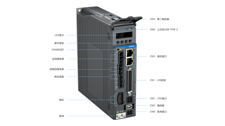
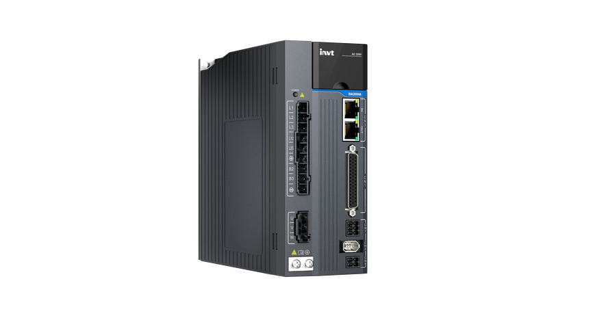
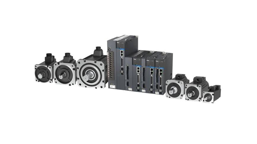
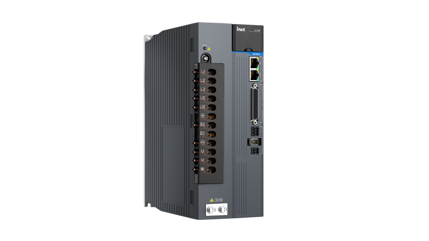
DA200A AC Servo Drives
DA200A is the new single axis AC servo in INVT servo portfolio based on the stable technology platform. It integrates the new direct drive motor control algorithms, and improves the dynamic performance, reliability and usability. With the excellent products and services, INVT offers you competitive products for your motion control solutions.
·1.0.2-7.5KW
·2.EtherCAT, CANopen, Modbus, PULSE, PROFIdrive, MECHATROLINK-III
·3.CE, UL, EAC, RoHS, STO SIL3


 Video
 Images
Overview
Features
Specifications
Downloads
More Resources
Case
Videos
More
Features

Rich interfaces
 Supports 5 types of communication bus protocols.Supports 4 types of encoder protocols (other encoder protocols are expandable).
01
Powerful functions
Supports various functions including full closed-loop control, load inertia identification, EOE, and positioning compensation.02
Strong power performance
Designed with 3× overload capacity.Supports control of multiple motor types including rotary motors, linear motors, and torque motors.03
Safe and reliable
Supports Safe Torque Off (STO), meeting TÜV SIL3 safety certification.Supports multiple hardware protections.Standard equipped with dynamic braking to prevent mechanical damage and ensure personnel safety.04
Ease of Use
Supports Type-C debugging interface.Supports one-key parameter auto-tuning, significantly reducing commissioning time.Simple operation, reducing operational complexity.05
Specifications
Downloads
By Type:
 Load More
More Resources





Have questions or need support?
Our professional team is here to help.


Inquiry
TOP
Popular Searches:
Repair Progress Tracking | Identity Verification
To protect your repair information, please verify using the mobile number reserved on the service order.
Verify with the reserved mobile number
Verify
SMS Verification Code *
If you cannot receive the code, please contact the after-sales hotline. 400-700-9997


Contact INVT
Get in touch with INVT. Our team will get back to you shortly.
Full Name *
Company Name *
Email Address *
Phone Number *
Country *
City
Inquiry Type *
Product Category *
Select the product you're interested in.
-
Industrial Automation
-
Network Power
-
PV & ESS
-
e-Mobility
Your Message / Requirements *
I have read and agree to INVT Privacy Policy and Terms of Use
Captcha *