1. Background
Construction elevators play a critical role in people, equipment, and material transfer at construction sites. Construction elevators have developed to a high degree of intelligence for the evolution from using power frequency to using variable frequency.
The mainstream construction elevator drive solutions available in the market often use the combination of common VFDs and braking resistors. However, the solutions are low efficient since the resistors generate heat to raise the temperature inside the lift cage in summer which affects the driver's operation and waste a great deal of power energy when the elevator is lowering.
2. INVT Goodrive300-29 VFD solution
Goodrive300-29 VFD can integrate the feedback rectifier and inverter to implement the power feedback to the grid and the accurate control of elevator lifting and lowering, with the advantages of safety, smoothness, stability, high efficiency, and energy saving.
2.1 Description of Goodrive300-29 feedback function

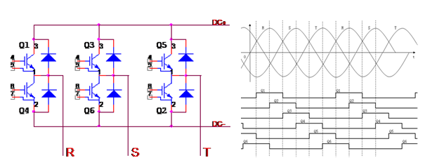
Figure 1 Feedback diagram
Figure 1 shows the work process of a six-pulse rectifier. In the figure, R, S, and T are voltages at three phases; Q1 is the upper IGBT of R phase, Q2 is the lower IGBT of R phase; Q3 is the upper IGBT of S phase, Q4 is the lower IGBT of S phase; Q5 is the upper IGBT of T phase, Q6 is the lower IGBT of T phase. After phase locking, the upper IGBT is turned on when the corresponding grid phase voltage is 30° past the zero point and turned off when it is 150° past the zero point, with a turn-on time of 6.666ms; the lower IGBT is turned on when the corresponding grid phase voltage is 210° past the zero point and turned off when it is 330° past the zero point, with a turn-on time of 6.666ms. As a result, the output PWM period is 20ms and the frequency is 50Hz.
2.2 Elevator action flow

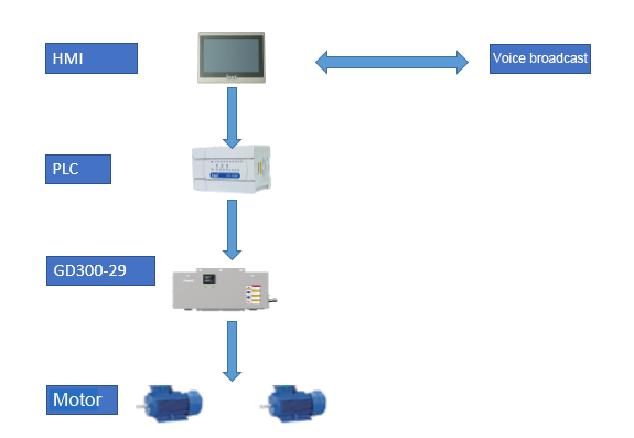
In this action flow, the elevator sends an instruction to the PLC through the operating handle, the PLC executes an action to control the feedback rectifier VFD according to the instruction, and then the feedback rectifier VFD drives two 13kW motors using the space voltage vector method. The two motors conduct lifting, lowing, and deceleration to stop operations on the rack of the standard section through the worm gear and worm reducer.
2.3 System topological graph

* HMI: provides interface display of field limit status, frequency conversion status, and working status of the construction elevator.
* PLC: provides the status of the construction elevator to HMI, voice broadcast system, control limit, brake, and other components.
* Goodrive300-29 VFD: drives the lift up and down, and feeds the electrical energy generated by the motor during lowering back to the grid.
* Motor: conducts lifting, lowering, and stop operation through the turbine and worm on the rack of standard section and has brake coils.
* Voice broadcast: provides voice messages for lift status and fault information
2.4 Advantages
* Integrated with dedicated filter function to decrease interference
* Able to convert kinetic energy into electrical energy to reduce energy consumption and eliminate resistor costs
* Equipped with input reactor as a standard configuration for high power factor
* User-friendly voice broadcasting and maintenance
* Step-less speed control with small mechanical loss in the absence of contactors
* Low grid shock
* VFD-controlled dedicated braking logic with a high safety factor
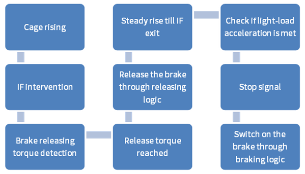
* Dedicated IF function to enables smooth rides
3. Our value to your business
INVT Goodrive300-29 series VFD solution has been applied on the construction elevator for more than 4 years. During this period, our products are market-proven and mature, which can serve your need for safety, smoothness, stability, high efficiency, and energy saving


Our site uses cookies to provide you with a better onsite experience. By continuing to browse the site you are agreeing to our use of cookies in accordance with our Cookie Policy.