Abstract: In order to meet the needs of masks during the special period of the epidemic, Jiefeng Machinery has developed a semi-automatic N95 mask edge welding machine system. It adopts manual discharging, frequency converter and indexing plate positioning, ultrasonic welding edge, and automatic cutting by robotic manipulator. The commonly used scheme is to use the servo drive with the electronic cam function to realize the master-slave synchronization and positioning, which is difficult to program and has a long development time period. Since Jiefeng Machinery only develops a single-station system and pursues a shorter development cycle, it chooses a frequency converter plus indexing plate to achieve positioning. The system is simple in process and programming, and can be quickly put into the production of masks.
Keywords: N95 mask edge welding machine , robotic manipulator , IVC1L ,indexing plate
1. Introduction:
The system includes an IVC1L PLC, VS HMI and GD20 VFD. 485 communication mode is used between HMI, PLC and VFD. Change the frequency through the HMI and change the motor speed. The motor rotates with the index plate and moves regularly in a stop-and-go manner. Prevent the impact of ultrasonic handpiece, manipulator and turntable. Add the inverter start-stop safety bit. PLC coordinates the actions of the VFD, ultrasonic module and manipulator cylinder.
2. Control requirements
The semi-automatic N95 mask edge welding machine system is divided into three parts, the first part is the feeding carousel station, the second part is the ultrasonic welding station, and the third part is the manipulator unloading station. Among them, the feeding station is controlled by Goodrive20 frequency converter with indexing plate. There are 6 stations in total. The N95 mask is manually folded and placed in the turntable mold. The ultrasonic station is an independent system, our PLC only needs to give the start and stop signals to the module. The unloading station of the manipulator consists of three groups of cylinders, the forward, up and down cylinders and the gripper cylinders. The coordinated actions of the cylinders complete the mask unloading.
The advantages of this system are:
* The development cycle is short, and it takes about 4 days for program writing, on-site debugging to normal delivery;
* Compared with the ordinary edge welding machine, the safety factor is high, and the running speed can be adjusted at any time in the running state.
* The post-maintenance is simple, the delay time of the action of the three stations, after the debugging is completed, there is no need to change it. Other devices also only need to directly copy the system parameters and delay time. As long as the mechanical and photoelectric switches are aligned, the equipment can be directly put into production without adjustment.
* VFD with indexing plate module:
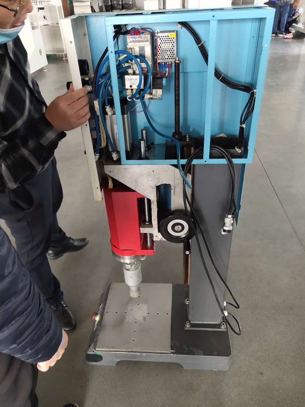
The working principle of the indexing plate: through the conjugate cam on the input shaft and the indexing plate with evenly distributed needle roller bearings on the output shaft, there is no gap and vertical meshing, and the curve section of the cam profile surface drives the needle roller bearing on the indexing plate Drive the index plate to rotate, the straight line section makes the index plate stand still and self-locking in positioning. The system has a total of 6 stations, and the positioning is completed every 60°. As long as the position of the ultrasonic handpiece and the abrasive tool is aligned mechanically, the periodic movement of positioning can be performed.

Figure 1. indexing plate module
* Ultrasonic edge welding module:
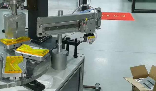
The ultrasonic module has its own controller, which realizes the spot welding action through the air cylinder and the sound wave start button. Our IVC3 only needs to start the switch signal for the ultrasonic wave.

Figure 2. Ultrasonic edge welding module
* Manipulator module
The manipulator completes the automatic unloading action, which is realized by the front and back, up and down and clamping jaw cylinders. Among them, the proximity switches are added to the front and rear cylinders and the lower cylinders respectively, which are used for the safety judgment position of the inverter's next action.

Figure 3. Manipulator module
3. System control realization
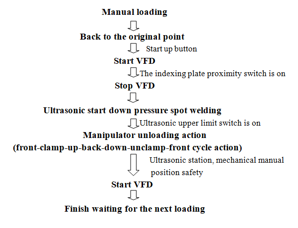
3.1. Process flow chart of N95 mask edge welding machine

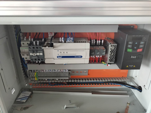
3.2. Electrical configuration
Name | Model | Qty. |
INVT PLC | IVC1L-2416MAT | 1 |
INVT VFD | GD20-0R75 | 1 |
INVT HMI | VS070HE | 1 |

Figure 4. Electric cabinet
3.3. Key parameters of the VFD
Function | Name | Value | Function | Name | Value |
P0.00 | Speed control mode | 2 | P2.06 | Motor Stator resistor |
|
P0.01 | Run command channel | 1 | P2.07 | Motor Rotor resistor | |
P0.03 | Max. output frequency | 80 | P2.08 | Motor Leakage | |
P0.04 | Upper limit of the | 80 | P2.09 | Motor Mutual inductance | |
P2.00 | Motor type selection | 0 | P2.10 | Motor Non-load current | |
P2.01 | Motor rated power | 370 | P5.01 | S1 terminal function | 1 |
P2.02 | Motor rated frequency | 50/60 | P0.06 | A frequency command | 8 |
P2.03 | Motor rated speed | 1400 | P14.00 | Local communication | 1 |
P2.04 | Motor rated voltage | 220 | P14.01 | baud ratio | 4 |
P2.05 | Motor rated current | 1.9/1.8 | P14.02 | Digital bit checkout | 1 |
P0.11 | Accelerate time | 0.1 | P0.12 | Decelerate time | 0.1 |
3.4. Debugging considerations
The acceleration and deceleration time of the motor is set at about 0.1s-0.2s. If the time is too long, the motor cannot be stopped in time, resulting in inaccurate station alignment. Setting the deceleration time too short may cause overshoot. Acceleration and deceleration time and indexing plate signals need to be accurately adjusted, so that the movements can be smooth and the work positions can be aligned.
4. Ending
The system is a semi-automatic mask machine, the production efficiency is not very high, but the mechanical cost and development cost are very low, programming and debugging took a total of 2-3 days, and can be quickly put into production. The main problem encountered during the test is the use of the ultrasonic module. The ultrasonic resonance welding joint cannot be designed casually. It is necessary to use the original welding joint or the welding joint tested by the manufacturer. The action is mainly the cooperation of the three cylinders of the manipulator, and the safety position can prevent the collision of the three stations.
5. Reference
[1] 《IVC operation manual V1.40》 SHENZHEN INVT ELECTRIC CO.,LTD.
[2] 《Goodrive 20 operation manual》 SHENZHEN INVT ELECTRIC CO.,LTD.


Our site uses cookies to provide you with a better onsite experience. By continuing to browse the site you are agreeing to our use of cookies in accordance with our Cookie Policy.