Abstract:A linear filling machine is an equipment used in automated production lines, mainly used to fill liquids, semi liquids, or powdered substances into containers at high speed and accuracy. Mainly suitable for the filling of tincture, syrup, ointment, various alcoholic beverages, oils, water reagents, general emulsions, suspensions, etc. in industries such as pharmaceuticals, medical, food, chemical, etc. It is a universal and stable automatic measuring and filling equipment. It can not only replace manual filling, but also conveniently link with other equipment to achieve full line automation.
Keyword:AX PLC , DA200 , ECAM , EtherCAT.
1. Project background
Linear filling machine is a device suitable for packaging liquid products, mainly capable of completing quantitative filling, capping and other processes. It has precise positioning, smooth operation, simple operation, high degree of automation, and a wide range of applications. It has functions such as no bottle filling, variable frequency speed regulation, etc. Therefore, it can be widely used in industries such as medicine, daily chemical, and food. At present, there are many types of linear filling machines, with the number of filling heads ranging from 2 to 10; The more filling heads there are, the higher the efficiency of filling. The straight filling machine with 4 filling heads is most widely used in the market. However, currently most manufacturers use speed control for their filling machines, which means that the filling head only synchronizes with the bottle speed during filling. It is difficult to ensure the accuracy of the relative position between the bottle and the filling head and the complete equality of the speed when clamping the bottle. When clamping the bottle, it is easy to cause the bottle to tilt, leading to waste of the filled item.
If there is a deviation between the filling head and the bottle position, manual adjustment through the HMI parameters is required, and the operation process is relatively cumbersome. Given the current problems in linear filling machines, INVT's application solution has been greatly optimized from the customer's perspective, resulting in simpler customer operations and more stable equipment operation.
2. INVT Application Cases
2.1 Principle of Linear Filling Machine Equipment
The linear filling machine has two modes: large bottle filling and small bottle filling. The filling head position is automatically adjusted according to the selected filling mode; The small bottle filling mode can also be divided into positive sequence four head filling, reverse sequence four head filling, two head filling, etc.; The linear filling machine has a bottle detection sensor that can automatically record the position of each bottle, and then automatically calculate the triggering position of each bottle according to the set filling head working mode and save it; The detailed control process is as follows:
Step1. First, select the filling mode of the linear filling machine, whether it is the large bottle filling mode or the small bottle filling mode;
Step2. Automatically calculate and plan the CAM curve of the filling head based on the selected mode and the actual mechanical parameters set, and automatically adjust the filling head to the corresponding position;
Step3. Set the capacity of the can, calculate the servo motion of the liquid injection based on the mechanical dimensions of the electric liquid injection device, and automatically adjust it according to the setting;
Step4. The bottle detection sensor records the position of each bottle detected based on the set filling mode, calculates the filling position of each bottle, and caches the calculated position into a defined array;
Step5. Real time monitoring of the actual position of the conveyor belt, comparing and triggering the corresponding filling head operation in real-time based on the position of each cached bottle;
Step6. Each filling head is equipped with a bottle clamp detection sensor. When the filling head is working, it will automatically determine whether there are bottles in that position. If it is determined that there are no bottles, filling will not be carried out; Avoiding waste of filled items;
Step7. After filling, when the bottle passes through the capping area, it will be detected and recorded by the capping area sensor. The recorded position will be cached and waiting for the capping device to be triggered to operate;
Step8.The capping part automatically calculates the Cam curve of the capping mechanical part based on the set mechanical parameters;
Step9. According to the position recorded by the capping area sensor, trigger the capping device to automatically tighten the caps of each bottle;
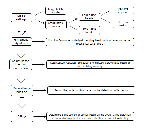
Equipment Control Process Flow Diagram
2.2 Filling head planning cam curve
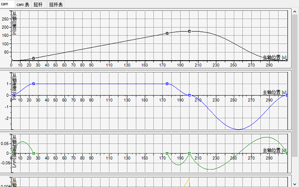
Filling cam curve
2.3 Scheme topology diagram
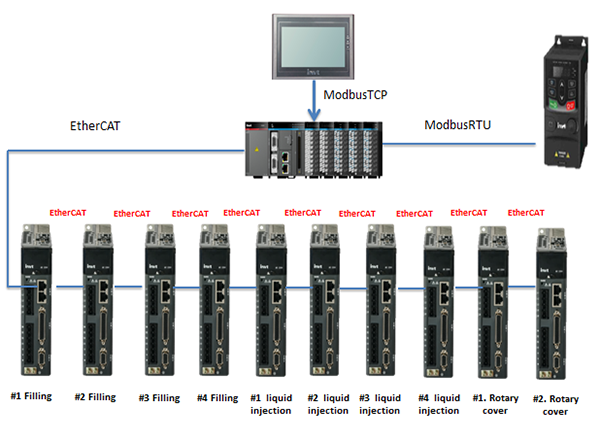
2.3.1 Scheme Configuration Table
1 | Controller | AX72-C-1608N | 1 |
2 | Power Module | AX-PWR | 1 |
3 | Digital Input | AX-EM-1600D | 2 |
4 | Digital Output | AX-EM-0016DN | 2 |
5 | HMI | VS-102QS | 1 |
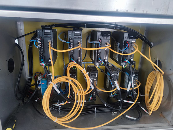
6 | Filling Servo | SV-DA200-0R7-2-N0 | 4 |
7 | Liquid injection servo | SV-DA200-1R5-2-N0 | 4 |
8 | Rotary cover servo | SV-DA200-3R0-4-N0 | 2 |
9 | Filling Motor | SV-ML08-0R7G-2-9A0-1000 | 4 |
10 | Liquid injection Motor | SV-MM13-1R5E-2-9A0-1000 | 4 |
11 | Rotary cover Motor | SV-MM13-3R0E-2-9A0-1000 | 2 |
12 | GD20-0R7G-S2 | 3 |
3. Advantages of the plan
* The bus scheme replaces the original pulse scheme, greatly reducing the number of wires, reducing the workload of customer engineers, and improving the production efficiency of equipment;
* Adopting ECAM control scheme, the equipment debugging is simple, the operating speed is improved, and the stability of the injection head and bottle position is ensured;
* When the equipment is running, it is allowed to modify the filling capacity. Customers can replace bottles of different specifications without stopping the equipment, which improves production efficiency
4. Customer revenue
* Replacing the solution originally used by the customer helped reduce electrical costs and improve product operability;
* Higher quality service shortened debugging cycle, and more convenient and efficient adjustment of process formula through visual cam table. After replacing the mold, the specifications can be automatically recognized, reducing the losses caused by manual operation and adjustment.
*Efficiency improvement and shortened filling cycle greatly enhance equipment competitiveness.
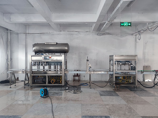
5. Equipment photos


Our site uses cookies to provide you with a better onsite experience. By continuing to browse the site you are agreeing to our use of cookies in accordance with our Cookie Policy.