Abstract: This article mainly introduces the mature application of INVT DA180A servo products in capacitor winding machines. The main focus is on achieving constant tension control for unwinding and rewinding of tin-zinc film materials through speed and torque mode control, addressing some customization requirements for unwinding and rewinding control in specific process scenarios.
Keywords: DA180A, Capacitor winding machine, Unwinding and rewinding
1. Introduction
Our solution is compared to other branded solutions eliminating the external control board, the number of external components is reduced, which greatly minimizes after-sales issues. In the unwinding control, the main method is constant tension control. The value of analog input AI1 and the external DI terminal control the servo enable signal. The analog AI1 input is used to set the servo torque, and the tension can be adjusted by switching the AI1 gain. The DO output sends a tension break signal, and the reverse speed parameter is used to recover from a material break and disable the enable signal. In the rewinding control, the primary function is the "near stop" feature in speed mode. The PLC controls the rewinding speed via AI2, and the zero-speed clamping position function prevents any oscillation caused by analog fluctuations during the near stop operation.
2. System Control Process
The control of the capacitor winding machine is divided into two parts: unwinding and rewinding. The unwinding part operates in torque mode, where the PLC controls the servo torque via an analog output to achieve constant tension. The rewinding part operates in speed mode, where the PLC controls the real-time speed of the rewinding servo through an analog output. In addition, the servo zero-speed clamping function is used to implement fixed-length winding and near-stop cutting features.
3. System Principle and Control Implementation
The control system is primarily divided into two positions: unwinding and rewinding.
Rewinding: For fixed-length winding, the PLC internally plans the position curve, and the speed signal is sent to the servo through AI2 in the form of an analog signal. The external IO controls the servo enable and zero-speed clamping functions. The actual on-site analog signal of -5V to +5V corresponds to the motor speed, with the corresponding AI2 gain set at 333%.
Unwinding: The unwinding speed is set to the maximum motor speed of 3500 rpm. In torque mode, the torque setting is controlled by the analog input AI1 and terminal gain selection. AI1 has four analog gain settings, selected via two digital inputs. The PLC uses AI1 to control constant tension.
The material configuration list is as follows:
No. | Name | Model | Pcs |
1 | 400W Servo drives | DA180A-E-2R8-S-2 | 6 |
2 | 400W Servo motors | IMS20B-06M40B30C-2-M4-J | 2 |
3 | 200W Servo motors | IMS20B-06M20B30C-2-M4-J | 4 |
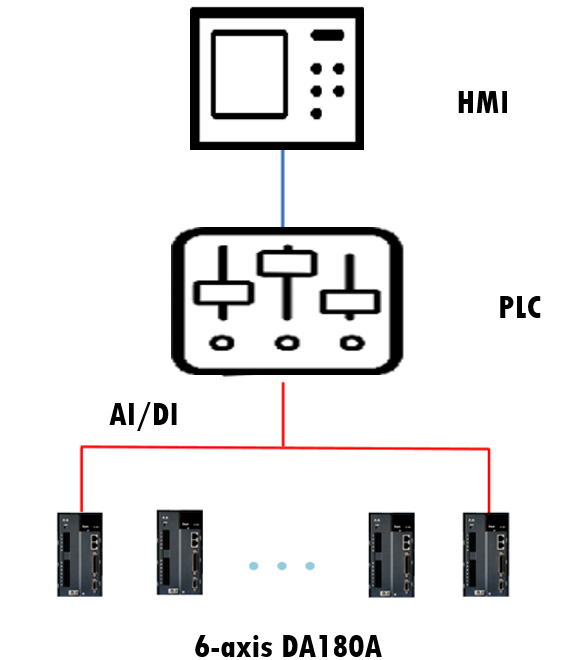
The system topology diagram for the on-site application is as follows:

System topology diagram
4. Winding and unwinding parameters setting
* Winding:
Function code | Name | Value | Description |
P0.03 | Control mode selection | 1 | Speed mode |
P0.40 | Speed command selection | 1 | Analog input |
P0.62 | Analog input 2 gain | 333 | 333% |
P0.67 | Speed limit mode | 0 | Internal give |
P3.00 | Input configuration of digital input 1 | 0x003 | Servo enabling |
P3.01 | Input configuration of digital input 2 | 0x10D | Zero-speed clamp |
P3.26 | Function of analog input 1 | 0 | Invalid |
P3.27 | Function of analog input 2 | 3 | Speed command |
P3.43 | Digital input filter | 4 | 4*125us |
P4.31 | Max. speed limit | 6000 | 6000rpm |
P4.96 | Encoder initial angle test | 1 | Test initial angle encoder only without zeroing |
P9.53 | PWM switching frequency | 2 | 16KHZ |
* Unwinding:
Function code | Name | Value | Description |
P0.02 | Forward rotation of motor | 1 | Clockwise is forward rotation |
P0.03 | Control mode selection | 2 | Torque mode |
P0.60 | Torque command selection | 4 | Analog input and terminal selection gain |
P0.46 | Speed limit 1 | 3500 | Max.3500rpm |
P0.95 | Terminal analog gain 1 | 100 | Low sensitivity |
P0.96 | Terminal analog gain 2 | 200 | Medium sensitivity |
P0.97 | Terminal analog gain 3 | 300 | High sensitivity |
P0.98 | Terminal analog gain 4 | 400 | Ultra-high sensitivity |
P3.00 | Input configuration of digital input 1 | 0x003 | Servo enabling |
P3.02 | Input configuration of digital input 3 | 0x039 | Torque command reversal |
P3.03 | Input configuration of digital input 4 | 0x037 | Analog gain selection 1 (low) |
P3.04 | Input configuration of digital input 5 | 0X38 | Analog gain selection 2 (high) |
P3.26 | Function of analog input 1 | 4 | Torque command |
P3.27 | Function of analog input 2 | 0 | Invalid |
P4.96 | Encoder initial angle test | 1 | Test initial angle encoder only without zeroing |
P9.53 | PWM switching frequency | 2 | 16KHZ |
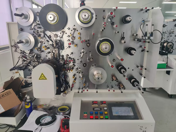
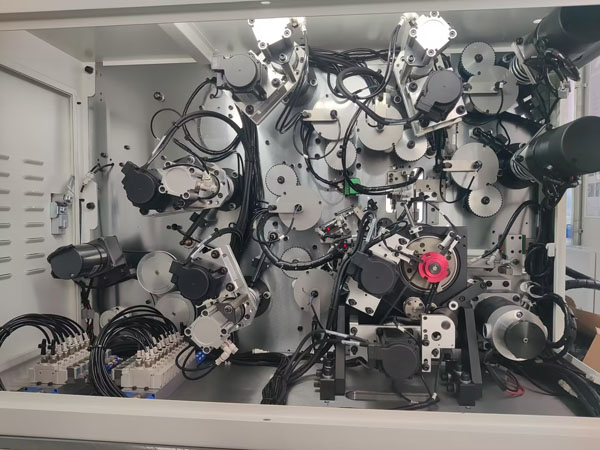
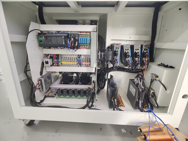
5. On-site Images

Overall figure

Back view

Electrical diagram
5. Conclusion
Our solution for the capacitor winding machine has low requirements for external components, with a high degree of customization integration. The speed response and noise performance are excellent, making it easy to replicate the solution within the industry. This solution has great potential for replication and promotion in this sector.


Our site uses cookies to provide you with a better onsite experience. By continuing to browse the site you are agreeing to our use of cookies in accordance with our Cookie Policy.