1. VFD-driven belt conveyor is the mainstream of industry applications
The belt conveyor is a continuous conveying machine that uses the conveyor belt as a traction and carrying material. The conveyor belt is wound around the driving roller and various reversing rollers, and is given appropriate tension by the tensioning device. During operation, driven by the driving device, the friction and tension between the roller and the conveyor belt are used to make the transportation. The material is continuously sent to the conveyor belt, and moves with the conveyor belt, so as to realize the conveying of the material.
Most of the existing belt conveyors are driven by power frequency, and there are direct-on-line start, hydraulic coupling start, soft start and so on. Due to the long-term power frequency operation of the motor and the efficiency of the hydraulic coupler, etc., the belt conveyor is very uneconomical to run; at the same time, due to the large impact of the motor starting, it will produce a violent impact on the machine and accelerate the mechanical wear; the wear and maintenance of the conveyor belts and hydraulic coupling will result in a large cost. This is incompatible with the creation of a low-carbon, energy-saving society today.
Due to the wide speed regulation range of the VFD and the large starting torque, it can start slowly under heavy load. For belt conveyors driven by multiple motors, the VFD has good master-slave synchronous control performance, and the master-slave control power is balanced. At the same time, the use of VFD has also significantly improved the power factor of the motor. After the logistics sensor is configured in the transportation system, the speed of the belt conveyor can be automatically adjusted according to the actual material flow demand, which is economical.
In general, belt conveyors are driven by VFD, which has very practical significance for saving social energy and increasing corporate benefits. VFD-driven belt conveyors have become the mainstream of industry applications.
2. Background of a mining belt conveyor project in Xinjiang
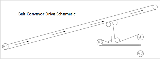
A mining company in Xinjiang built a new 101 belt conveyor project. It is an upward belt with a length of about 6km. It is driven by 4 medium-voltage permanent magnet synchronous motors with a specification of 10kV/1400kW. 3 motors at the head and 1 motor at the tail. The driving diagram of the belt conveyor is as follow: the head motors M1 and M2 drive the same drum, and M3 drives the reversing drum. The head motors M1, M2, and M3 are very close together and are regarded as rigid connections. There is a 6km long belt between the three motors at the head and the motor M4 at the tail, which is regarded as a flexible connection.
Belt design requirements are as follows:
1. Permanent magnet synchronous motor:
U=10kV, N=1400kW×4 (3 heads and 1 tail), n=74r/min
2. Tape width: B=1600mm,
Capacity: Q=4000t/h, speed: V=5.5m/s
3. Length: L=6290m, Lifting height: H=45m
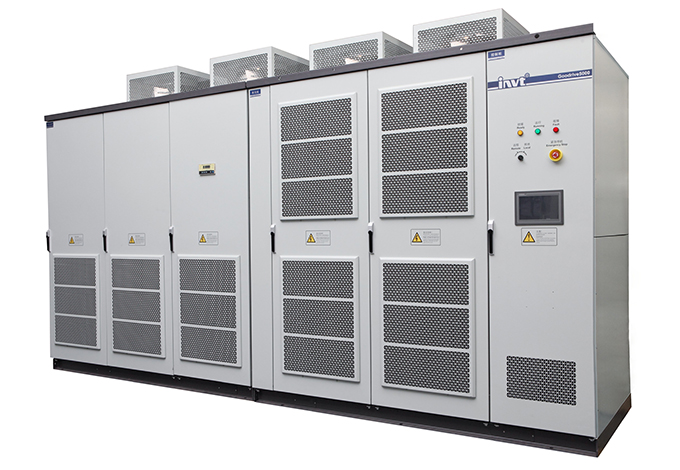
3. INVT medium-voltage drives solution
According to customer needs, INVT provides a master-slave control solution for GD5000 medium-voltage inverters. The solution is equipped with a long-distance optical fiber communication module to meet the requirements of long-distance optical fiber communication between the head and tail inverters.
GD5000 control system adopts DSP+FPGA+ARM multi-core control system, and adopts advanced speed sensorless vector control method, which is suitable for high-voltage asynchronous and synchronous motor speed regulation. High control precision, fast dynamic response, and large output torque at low frequency; master-slave control technology can realize coordinated control of multiple motors and achieve power balance.
3.1. Introduction to the master-slave control scheme
The master-slave control of 3 inverters at the head and 1 inverter at the tail adopts optical fiber communication. The optical fiber connection method is a ring connection, and the optical fiber interface is located in the inverter control cabinet. The inverter itself can achieve power balance through master-slave control.
The way to achieve power balance is to report the output power of the slave inverter to the master inverter through high-speed communication. After the master inverter analyzes, judges and calculates, adjusts the operating frequency of the slave inverter to achieve the output power of two or more inverters. Basically the same, the power error is controlled within 5%.
The 4 MVDs all adopt vector control. The 3 motors in the head are rigidly connected, the No. 1 is the master, which adopts speed control, and the two slaves, No. 2 and 3, adopt torque control. The No. 4 motor in the tail and the head are regarded as a flexible connection, and speed control is adopted.
The main parameters are as follows:
1# Master | 2# Slave | 3# Slave | 4# Slave | |||
Function code | Name | Setting value | Description | |||
P00.00 | Control mode | 2 | 2 | 2 | 2 | 2: SVC mode 1 |
P00.01 | Control Command chanel | 1 | 3 | 3 | 3 | 1: Terminal |
P00.05 | Speed reference | 0 | 3 | 3 | 2 | 0: Speed mode |
P02.00 | Motor type | 3 | 3 | 3 | 3 | PMSM |
P02.11 | Rated power of PM motor | 1400kW | 1400kW | 1400kW | 1400kW | Set according to motor nameplate |
P02.12 | Rated frequency of PM motor | 50Hz | 50Hz | 50Hz | 50Hz | |
P02.13 | Rated rpm of PM motor | 75 rpm | 75 rpm | 75 rpm | 75 rpm | |
P02.14 | Poles pair of PM motor | 40 | 40 | 40 | 40 | |
P02.15 | Rated voltage of PM motor | 10000V | 10000V | 10000V | 10000V | |
P02.16 | Rated current of PM motor | 87A | 87A | 87A | 87A | |
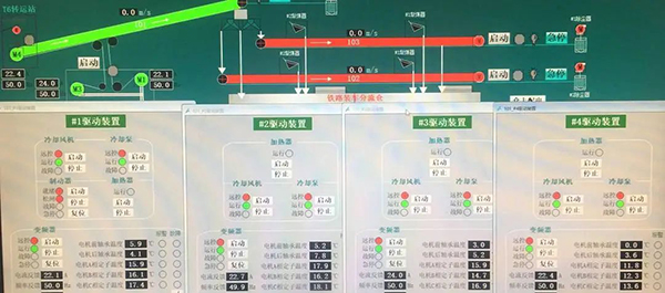
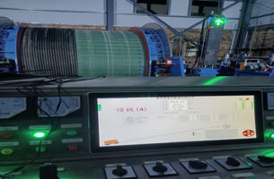
3.2. On-site operation status
The equipment debugging is completed, the speed of the 4 motors is synchronized, and the power is balanced. When running with material, the difference of motor running current is about 1A, and the running effect is highly recognized by users.
3.3. On-site photos
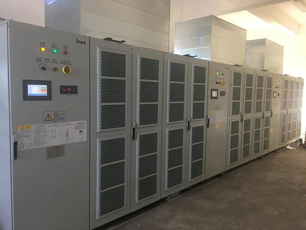
3 MVDs at the head side
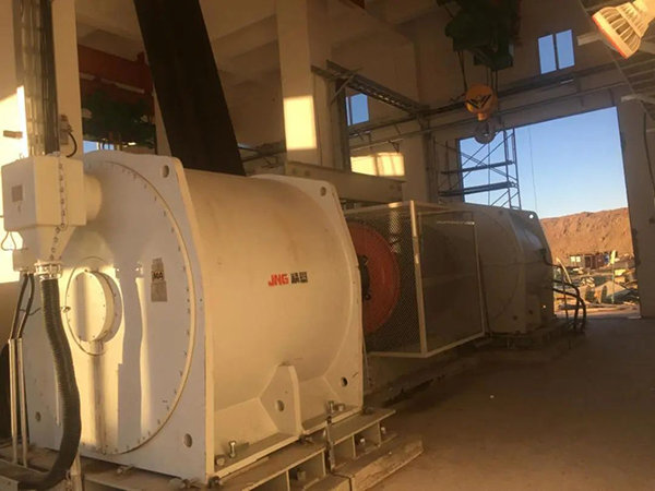
Head motor M1 and M2
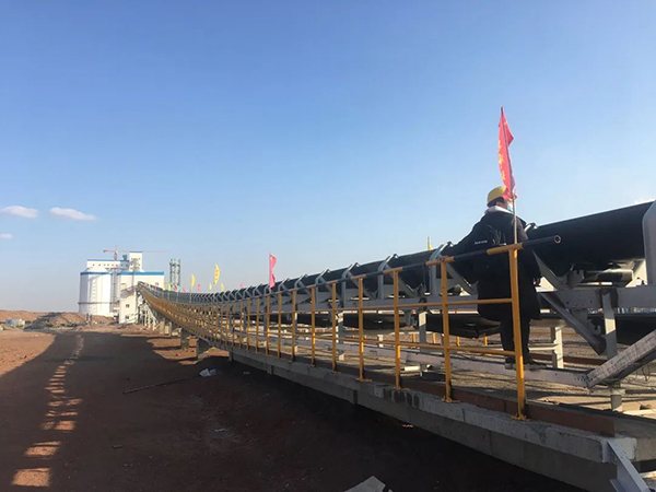
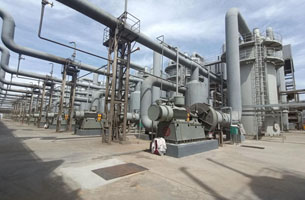
Belt conveyor
4. Conclusion
In this belt conveyor project, the load motor are medium-voltage permanent magnet synchronous motors, and the master and slave motors have both rigid and flexible connections. The software control performance of the GD5000 inverter has been fully tested. The distance between the head frequency conversion and the tail frequency conversion is about 6 kilometers. The long-distance optical fiber communication and the long-distance transmission reliability and stability of the control signal have also been verified. It has been proved by practice that the master-slave control scheme of INVT GD5000 high-voltage inverter fully meets the requirements of on-site use.
The successful application of INVT's advanced multi-motor master-slave control technology on the belt conveyor reflects the company's strong technical strength in the mining industry. Mature solutions, excellent product performance, and good on-site service are highly recognized by customers.


Our site uses cookies to provide you with a better onsite experience. By continuing to browse the site you are agreeing to our use of cookies in accordance with our Cookie Policy.


 Share
Share
 Facebook
 Twitter
 Google+
 LinkedIn
 Return list